 Printed Circuit Artwork
PCB Artwork is not for Machines!
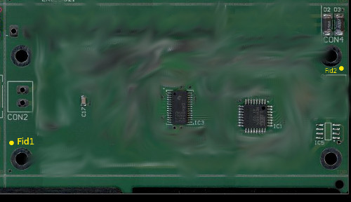
Small scale production environments or protyping designs may incorportate artwork in the PCB design. Well designed artwork almost always provides no advantage for machines or their programmers but often problems. Shown here is a design that will provide a small help and we will discuss the possible problems.- The yellow indicates how you could help a machine programmer. Give the fiducial enough space to include text indicating it's number. This will help the programmer especially if you have provided in your CAD data co-ordinates for these fiducials.
- In the center of this PCB is a udg28_65p80x19 or one of the ssop28s. The artwork of this component is worth noting. Here we have the corners shown, polarity indicated and the name of the components position (IC3). This artwork is a good example of artwork that does not compromise optical testing of the component. The artwork for IC5 will be borderline problematic. Testing for solder bridging (shorts) naturally occurs between the pins of ICs. Should white lines be visible at the edge of the component the programmer will have to limit the testing of shorts to outside of this area. Often solder bridging can take place directly against the components body.
Remove Artwork from areas to be tested for solder bridging (shorts)!
 Printed Circuit Artwork