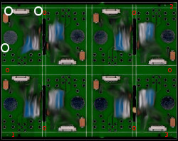
 PCB Panel example
- Here is a rather new panel I have worked with. I have smudged the inner area of components where there was no convenient area for fiducials. The panel design is worth noting for several good and bad points.
- Panels should have 3 fiducials and the two diagonal from each other should not be symmetrical. The purpose is to eliminate the possibility that a machine accept the board if it is turned. Some machines like an Orprovision accept only two fiducials and following the rule of using the greatest separation we are left with fiducial 1 and 2 in this case. Since the second fiducial is further away from it's board edge than fiducial 1 the machine will not locate this panel when turned. Other machines can simply use all 3 fiducials to eliminate confusion and increase accuracy.
- Between the PCBs you can see that they have been routed/milled. Should the Pcb's edges need to be smoother than the edge left after the break-off strip is removed routing the necessary edges when making the PCB can be done. Naturally this has some restrictions and should be discussed with the PCB manufacturer.
All PCBs should have Fiducials
There are many reasons why you should include fiducials on all PCBs. Some complications are, panels can be susceptible to shrinkage not always equal in x and y directions, panels may be processed incomplete or in pieces, that the accuracy needed is more than global fiducials provide (fine-pitch). Some manufacturing processes create faulty PCBs in panels. Fiducial marks are a sometimes convenient way to deal with these faulty or bad board PCBs. The panel shown above does not have fiducials for the PCBs but there is significant area shown by the three white circles where fiducials could have been added.Remember the 5mm Edge Rule
This designer has gone to some effort to create this design but has forgotten one of the most important rules. The existing fiducial marks are not usable in some machines and border on usable in others. The outermost edge of the fiducial should be 5mms from the panel or PCB edge. If the designer wished to keep the tool strips at their existing size he could have moved the fiducial marks inside to the separation strips. I have indicated good possible locations with the red circles. Once again, "Usable fiducial marks are much better than maintaining the maximal separation!"
